
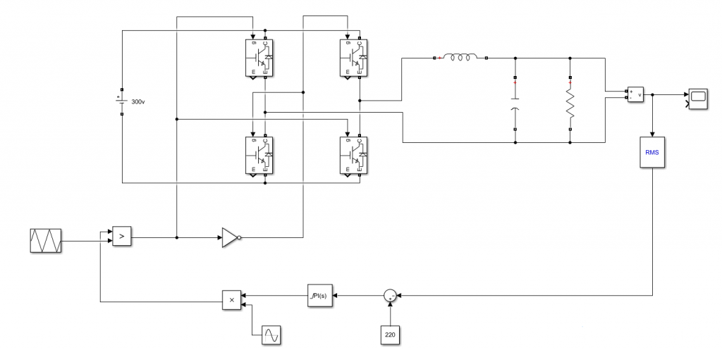
使用MATLAB仿真电压闭环的单相逆变电路
前情提要: https://lyphix.im/?p=328
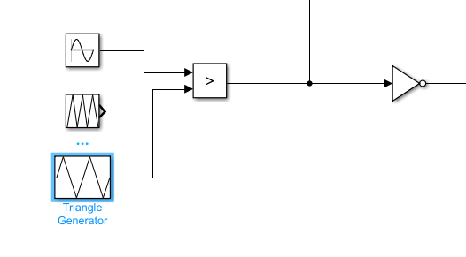
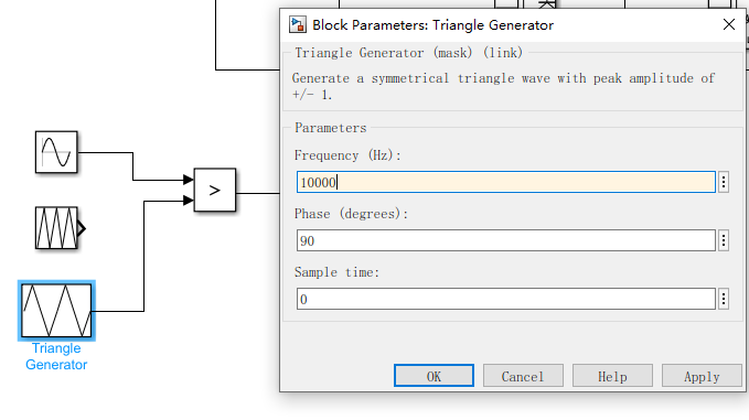
在添加闭环之前,我发现Siumlink中有Triangle Generator,比Repeating Sequence更方便设置三角波。因此我们替换一下
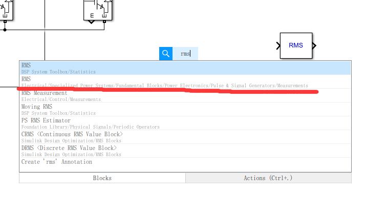
1.闭环采样设置
双击空白的地方,搜索RMS模块(有效值),注意我们需要使用的Electrical的RMS,一般是第二个,如图
将该模块连接到电压检测上
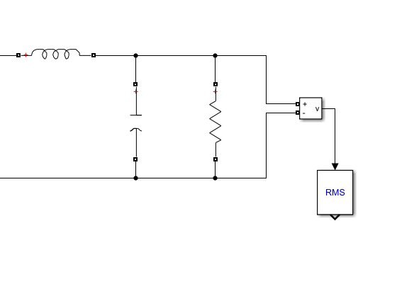
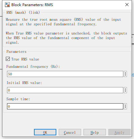
之后设置RMS的参数
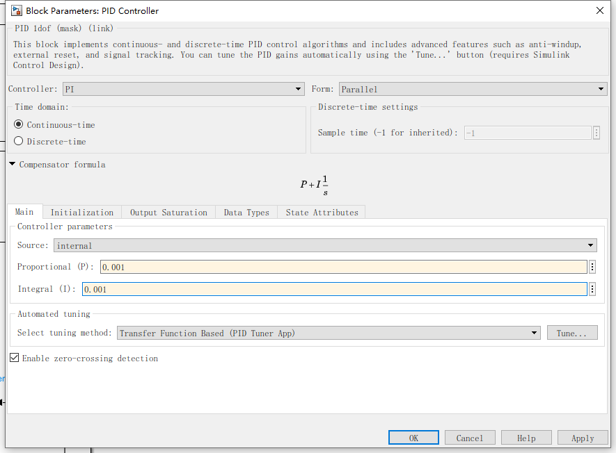
2.接入PID控制器
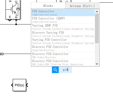
搜索PID,放置一个PID控制器
搜索constant,放置一个常数,作为给定

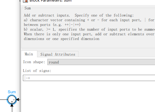
搜索sum加法模块,修改为-+,计算偏差
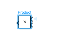
搜索product,添加乘法模块
最后将他们都连接在一起,RMS接-,220接+
3.整定PI参数
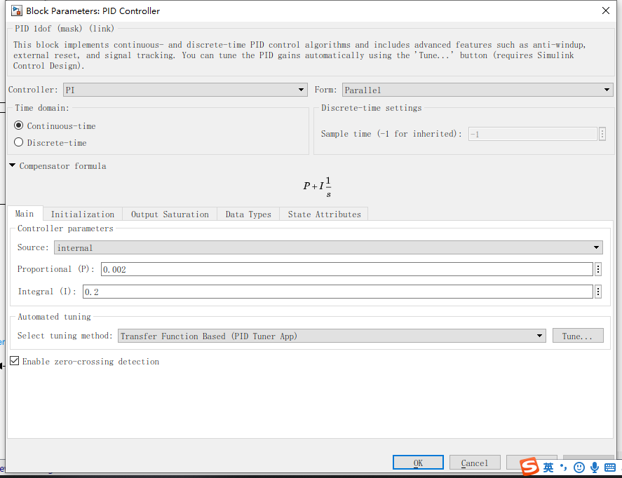
首先先将PID控制器设为PI,将PI参数设的尽可能小
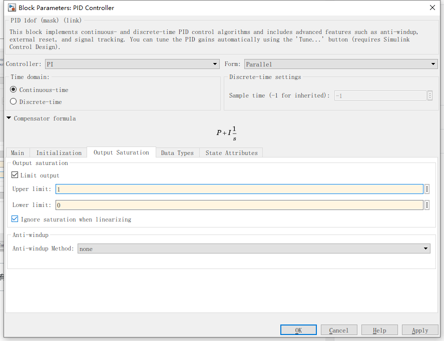
接下来我们限制一下输出,因为我们调制波只有在乘0~1之间有意义,最低是0,最高是1
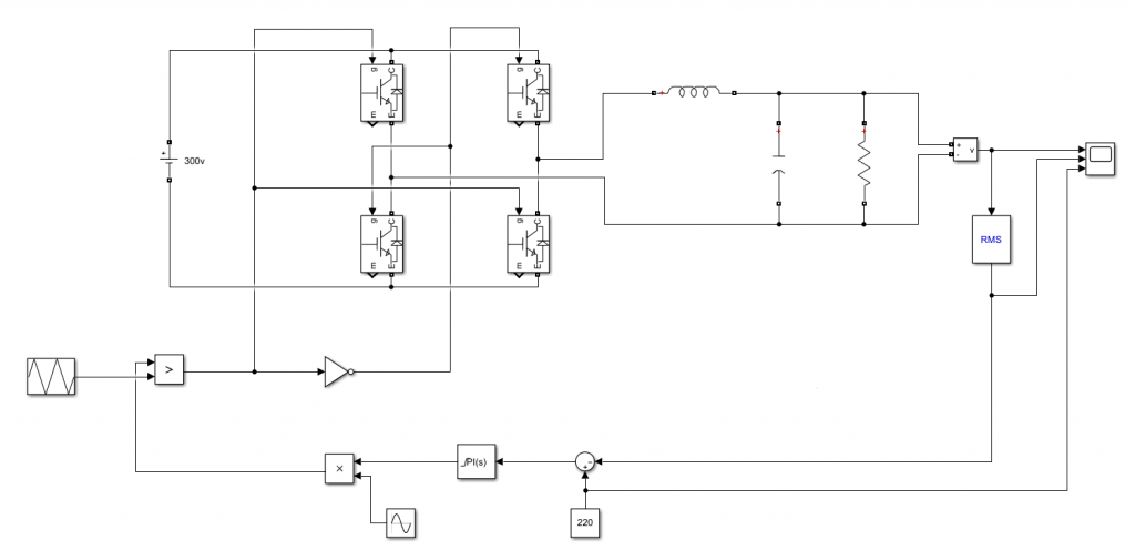
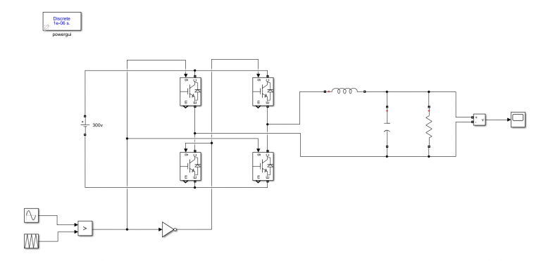
对电路图进行一些微调,添加示波器观测
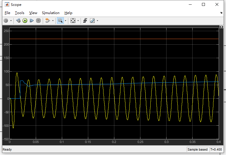
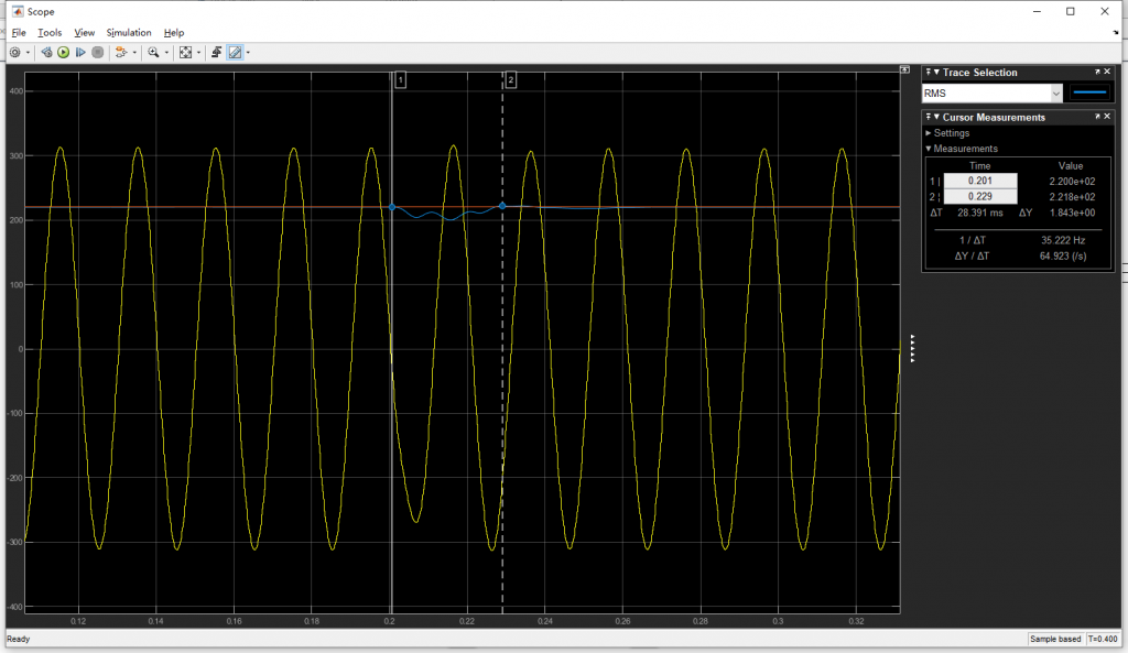
那么来进行第一次仿真,时间设为0.4秒,结果如图
橙色为给定,蓝色为有效值,黄色为正弦波形。可以看出PI值都太小,导致调节过慢
经过不断调试,使用以下PI值表现的性能还不错,当然你也可以继续调整
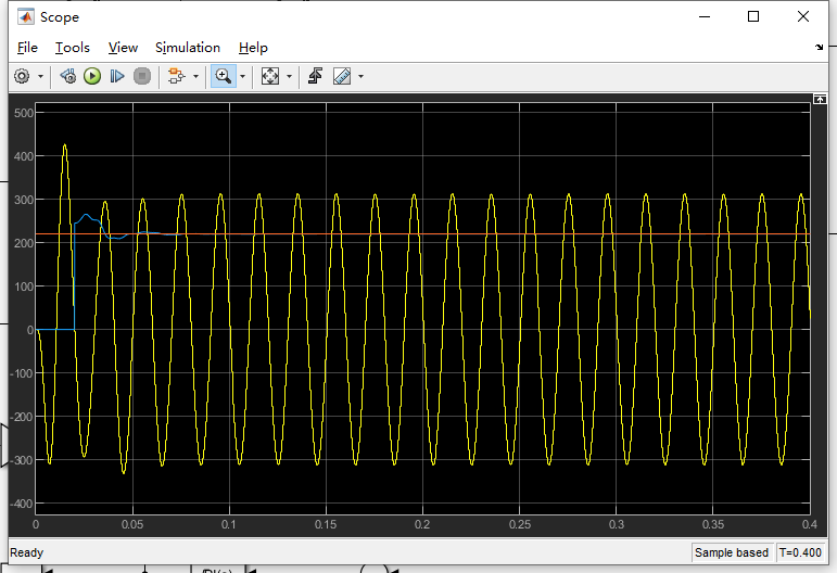
4.添加一些扰动,测试一下
搜索Breaker,添加一个断路器作为扰动
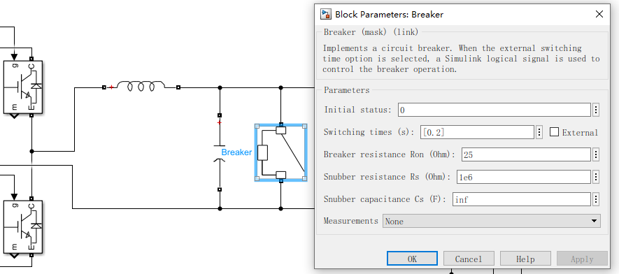
闭合电阻25欧,相当于负载电阻从100欧降至20欧
仿真如下
下一篇将会添加电感电流内环的双闭环仿真
众皆佬,独我菜。枯了。
我也菜的